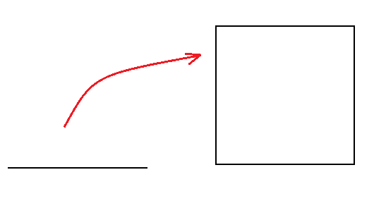
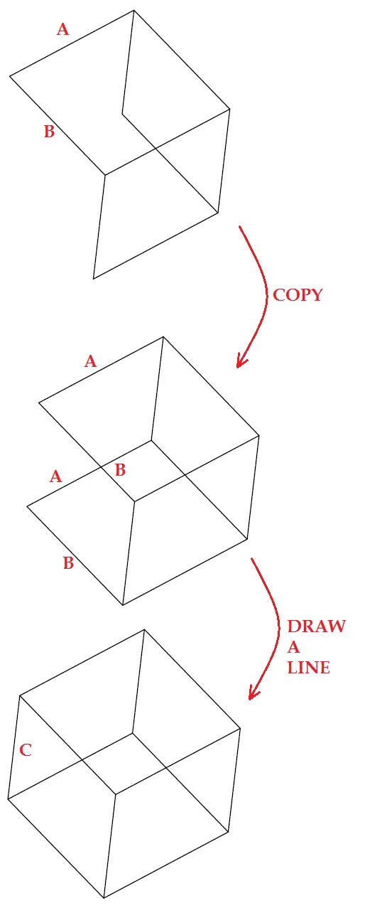
UCS stands for User Coordinate System and is represented by the object on the left down corner of your AutoCAD windows. This is a crucial tool for 3D design in AutoCAD. This is why in this post I will use the simple figure below to help you have an idea about how mastering UCS will enhance your ability to draw in 3D in AutoCAD.
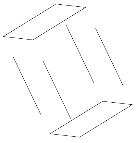
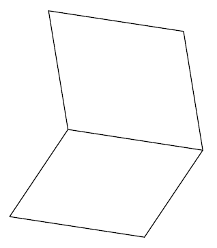
This image is just 12 lines of the same length arranged in space in a way to look like a cube. The top and down squares detached from the horizontal part will look like this:
Would you call this a 3D object?
Let’s Use the UCS rotation features and the World Coordinate System (WCS).
Step 1
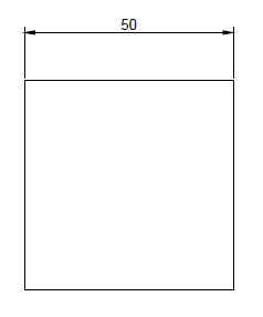
Open a new project and draw a square of 50 X 50
Step 2
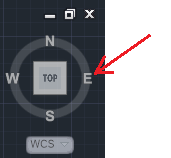
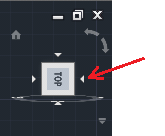
Use the WCS. Click on East.
step 3
Type
- UCS
- y
This is how it should look like when you follow what it’s been written in the command window. The part in Bold is what you are supposed to write.
Command: ucs
Current ucs name: *WORLD*
Specify origin of UCS or [Face/NAmed/OBject/Previous/View/World/X/Y/Z/ZAxis]
<World>: y
Specify rotation angle about Y axis <90>: “hit ENTER”
Step 4
Draw the 3 other lines to close the square. (Make sure ORTHO is activated)
What we have already drawn is this.
lets continue…
Step 5
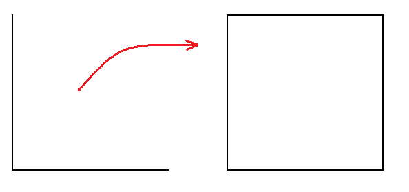
Click on the right side of the WCS
Step 6
Repeat step 3 but use x instead of y.
Step 7
Draw the 2 other lines to close the square like in step 4
Step 8
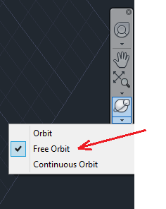
Use the Free Orbit to place the object such as you can be able to finish drawing the remaining part.
Once there, you can use the COPY command to finish drawing our cube.
The UCS rotation feature is one among many ways you can use while drawing in 3 dimensions in AutoCAD. It is important for any one desiring to master 3D to know how to use this feature.


