In Part 1 of this 2-part SolidWorks configuration tutorial, we will cover how to create multiple configurations for a part file. We’ll create two designs on the top rail component of a wooden chair model for use later on in an assembly file in Part 2 of this tutorial.
Configurations are used in SolidWorks to create multiple versions of a single file – whether it be a solid part or assembly. This is an excellent tool for enabling or disabling features, mates, or other properties, to represent various versions of your design without taking up extra space or creating redundancies.
It’s a flexible and streamlined method for creating multiple versions of a design within a single file. Perhaps the best way to understand how this works is with an example; let’s get started!
SolidWorks Configuration Tutorial: Step-by-step
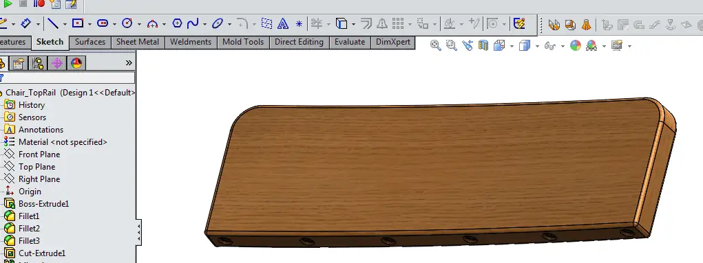
In this example, we’ll start with a simple wooden chair top rail model.
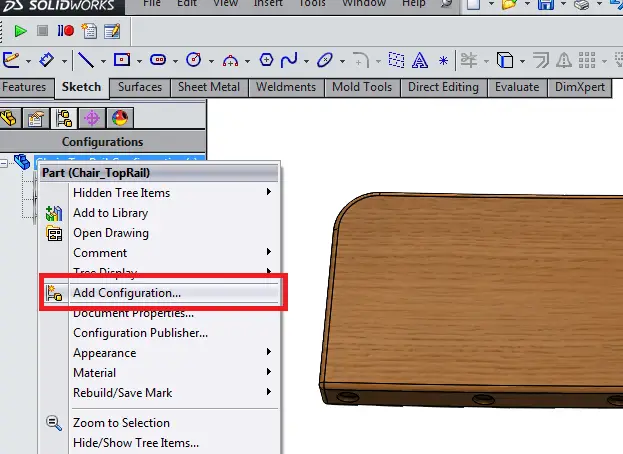
The first thing we’re going to do is switch to the Configurations tab (3rd from the left) in the upper right hand corner of the feature tree window on the left side of the screen.
Right click on “Chair_TopRail Configuration(s)” – or the name you’ve given your model – select “Add Configuration…”
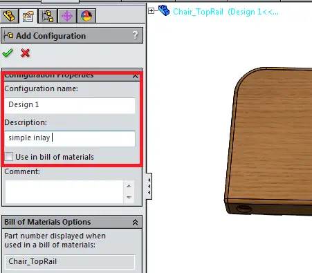
Now, give the Configuration a name. In this case, we’ll call it “Design 1.” You may also write a short description or longer comment in the given input fields. Notice also that you have other options, such as how to display certain information about the part in a Bill of Materials, if needed. This is outside the scope of this particular tutorial, but keep in mind that Configurations are a fairly powerful tool with a lot of very useful options!
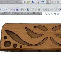
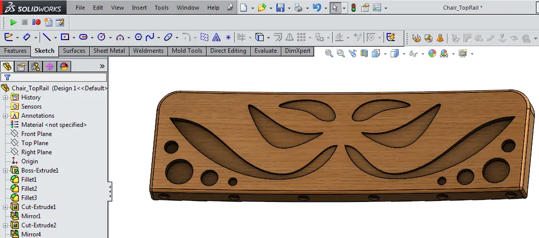
With the new configuration created, we’ll now move back to the feature tree tab. I’ve created a simple design on the front surface of the part using an Extrude Cut feature and a Mirror feature, for symmetry.
Now, move back to the configurations tab, and create an additional configuration, using the same method described above. This time, I’ve called it “Design 2.”
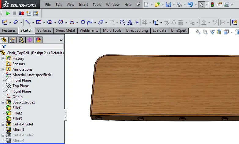
Once you’ve done this, move back to the feature tree and suppress the two features just used to create the simple design in the previous configuration. The part should now look just as it did before any additional features were added.
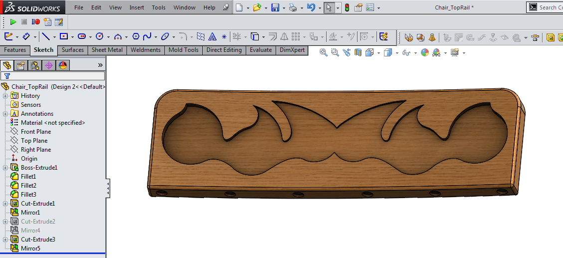
Now, I’ve created a second set of features – again an Extrude Cut and Mirror – and produced a second design on the front surface of this wooden chair part. This represents the “Design 2” configuration.
Final Results
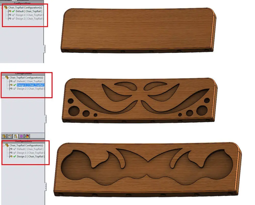
And we’re basically done! Notice that if you go back to the configurations tab, you can activate any one of the three configurations – Default, Design 1, or Design 2 – to show the different designs on your parts. This is accomplished by the fact that features within each configuration are suppressed or unsuppressed depending on the given configuration.
Tip: If any of the features you created shows up on the wrong configuration – simply select those features and suppress them in that configuration. By default, SolidWorks suppresses new features and mates as in new configurations. You can also toggle this feature in the ”Advanced” drop-down menu by right-clicking on any given configuration on the configuration tab and selecting Properties.
In Part 2 of this SolidWorks configuration tutorial, we’ll put this part to use in an assembly, and use configurations in that file to activate these configurations at the part level!
Are you interested in becoming an expert in SolidWorks? If you are a beginner or expert, you can benefit from an extensive course designed to get you ready for SolidWorks certification. We are giving a 75% discount on this course currently. Check it out below:


Comments
2 responses to “SolidWorks Configuration Tutorial – Part 1 of 2”
[…] Part 1 of the SolidWorks Configuration Tutorial, we covered how to create multiple configurations for a […]
I have imported a solidworks part in Autocad. How do I change configurations?