This is an exercise which is solved just for the purpose of comparing two numeral methods and see which one of them is more accurate.
Here we will be using Matlab to solve the equations with two different methods, which are:
Second order Runge Kutta method
and the inbuilt matlab function ode45 (which is by the way using the same Runge kutta method but to a higher order)
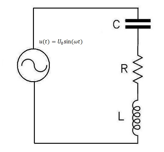
We will consider having to solve the RLC circuit below. We are required to find how the current varies with time in the circuit and we are given initial conditions.
Initial conditions
(The voltage here is the Capacitor voltage)
We will consider in this exercise:
Finding and derivation of equations from the RLC circuit.
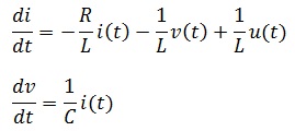
Using KVL and the capacitor voltage in the circuit, we will get the following system of equations.
It is to be noted that
Bringing all these information together, the Matlab code will look like this.
ode45 Matlab code
function xp=myode(t,x)
xp=zeros(2,1);
c=0.0001; % capacitance in F
U0=100; % input peak voltage
L=1.5; %inductance in H
R=50; % resistance in ohm
w=0.3/sqrt(L*c);
xp(1)=U0*cos(w*t)/L-R*x(1)/L-x(2)/L;
xp(2)=x(1)/c;
%%
%
%  An example of how it is used it stated below
%  [t,x]=ode45(@myode,[0,1],[0,1]);
%   where [TO TF], [I0 V0]
%   plot(t,x(:,1))
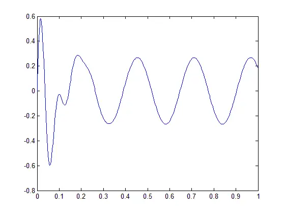
Resulting Plot

Runge Kutta Matlab code
i0=1;            % initial current, in A
v0=0;            % inital voltage on capacitance, in V
A=100;           % Amplitude of source
U0=A;            % initial voltage of source
L=1.5;           % inductor, in H
C=0.0001;        % capacitance, in F
R=50;            % Resistance, in ohm
w0=1/sqrt(L*C);  % Resonance frequency of LC circuit
w=0.3*w0;
h=0.005;         % time step, in s
N=200;           % Total number of time steps
i2=zeros(1,N+1);
v2=zeros(1,N+1);
t=zeros(1,N+1);
t(1)=0;          % Initial value of time
i2(1)=i0;        % Initial value of current
v2(1)=v0;        % Initial value of voltage on capacitance
U(1)=U0;
for n=1:N
    t(n+1)=n*h;
    U(n)=A*cos(w*t(n));
    U(n+1)=A*cos(w*t(n+1));
    % RK2 method
    k11=-R/L*i2(n)-1/L*v2(n)+1/L*U(n);
    k12=1/C*i2(n);
    k21=-R/L*(i2(n)+h*k11)-1/L*(v2(n)+h*k12)+1/L*U(n);
    k22=1/C*(i2(n)+h*k11);
    i2(n+1)=i2(n)+h*(0.5*k11+0.5*k21);
    v2(n+1)=v2(n)+h*(0.5*k12+0.5*k22);
end
hold on
plot(t,i2,'k*')
Resulting plot
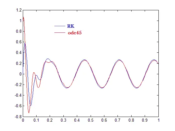
Combining both plots on the same graph
We see that our Runge Kutta method is slightly different from the ode45 Matlab function. Since ode45 uses a higher order of the Runge Kutta method we can conclude that ode45 is more accurate than the Runge kutta second order method.


