If you’ve already learned how to create a part in SolidWorks, it may not be long until you need to actually use that part in relation to other parts. In SolidWorks, this structure is called an Assembly.
An Assembly is comprised of one or more SolidWorks Parts or Assemblies, and is used to model relationships between these subcomponents or subassemblies using relationships called Mates.
In this tutorial, we’ll take a look at how you might use an assembly to create a basic coffee table. We’ll go through some very basic Mates, as well as cover some of the general properties of an Assembly file.
Use Assemblies to Create a Coffee Table
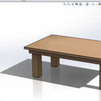
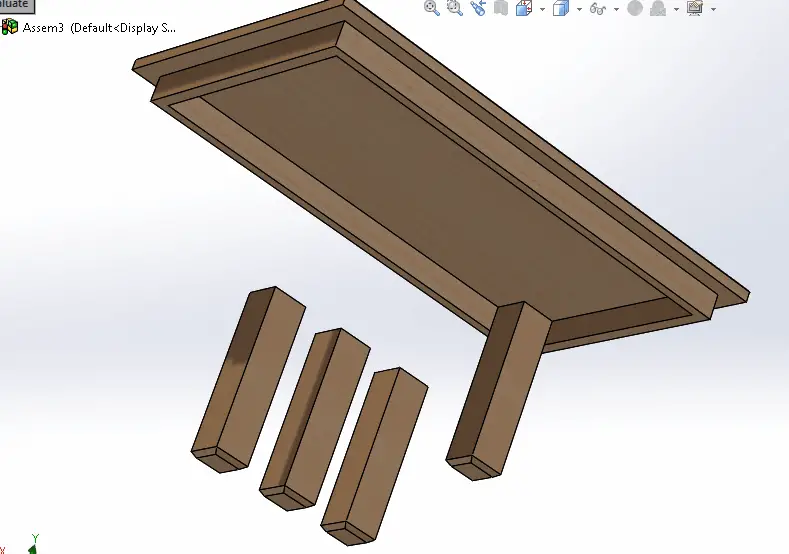
In this case, our coffee table assembly is comprised of five components – one top, and four legs. Let’s assume that at some point, we need to make an assembly file showing how these legs connect to the tabletop to form the full assembly. This assembly might later be used for things like photo rendering, assembly documentation, or a design review.
There are two SolidWorks part files which will define the five parts that make up this this assembly – a leg, and a table top. Four instances of the same leg solid part file will be used in our assembly.
Start by opening up both the table top and table legs SolidWorks part file.
Add Parts
Then, take the following steps:
- Select File > Make Assembly from Part;
- A new window opens with a panel to the left; click the pin icon to keep this open;
- Select a component, in this case the table top, and drag it into the work area;
- It will appear in the work area. Now select and drag out one of the legs;
- Move the mouse and click three more times to create a total of four instances of the legs.
Now, your work area should have all five components of the table, floating in space. Now, we will use a series of Mates to align the parts and make the assembly.
Explanation of Mates for Assemblies
Think of Mates as the geometric constraints or rules that govern the relationship between geometric entities on each of the subcomponents or subassemblies in an assembly. Mates can be applied to points, edges, or faces of solid entities.
Notice that mates don’t necessarily “freeze” a component – after all, mates may be thought of as properties establishing the type and number of degrees of freedom, or lack thereof, established among the geometry of a set of components. Mates can even be used to define an angular range, for instance, within which a part can move.
In this case, we will be using simple Coincident mates to form the assembly. Take the following steps:
- Select the square top face of one of the legs.
- Select Insert > Mate;
- Select Coincident;
- Select the face of the underside of the table;
- Notice that the leg moves to meet the same plane as the underside of the table;
- Create Coincident Mates for two side faces of the leg to meet the faces inside the trim of the table top.
- Repeat this process for all four legs.
Congratulations! You’ve created an assembly from a set of SolidWorks parts. Notice that you can see the parts that comprise the assembly in the assembly tree to the left side of the screen, much like the way that sketches and features comprise part file.
We hope you learned how to make an assembly in SolidWorks. Try to apply this technique in other SolidWorks tutorials.


Comments
2 responses to “How to Make an Assembly in SolidWorks – Tutorial”
[…] in SolidWorks to create multiple versions of a single file – whether it be a solid part or assembly. This is an excellent tool for enabling or disabling features, mates, or other properties, to […]
[…] are inevitably times when you’re using SolidWorks and have a great part or assembly, but would like to be able to turn on or off various parts, features, mates, or other properties […]