Now that you know how to add parts into your schematic, you are ready to learn the process of connecting these parts electrically. In Eagle, this is known as nets. Similar to the process in real-life (e.g. breadboard) where you make make electrical connections between parts, Nets allows Eagle to understand how the circuit is built. It is a simple procedure and I will use an example of a voltage divider with two resistors for illustration purposes. Let’s begin learning how to draw an electrical connection.
Explanation of the Example: Voltage Divider

Even though the example is just a way to show the process of adding nets, I will briefly explain a voltage divider. A divider requires two resistors as components connected in series.
These components receive an input voltage and are connected to ground. Between the two resistors is where the output voltage is taken. An example of this is shown in Figure 1 on the right and more a detailed explanation can be found here.
Adding the Parts into the Schematic
The first step is to create a new schematic file. After doing so, you need to add these parts:
- Resistors (2)
- Voltage input, VCC (1)
- Ground, GND (1)
The name of the component is shown along with the number of parts needed in parenthesis. Using the ‘add a part’ window, you can either search or look through the libraries to find the parts. I covered this process in a previous tutorial in much more detail.
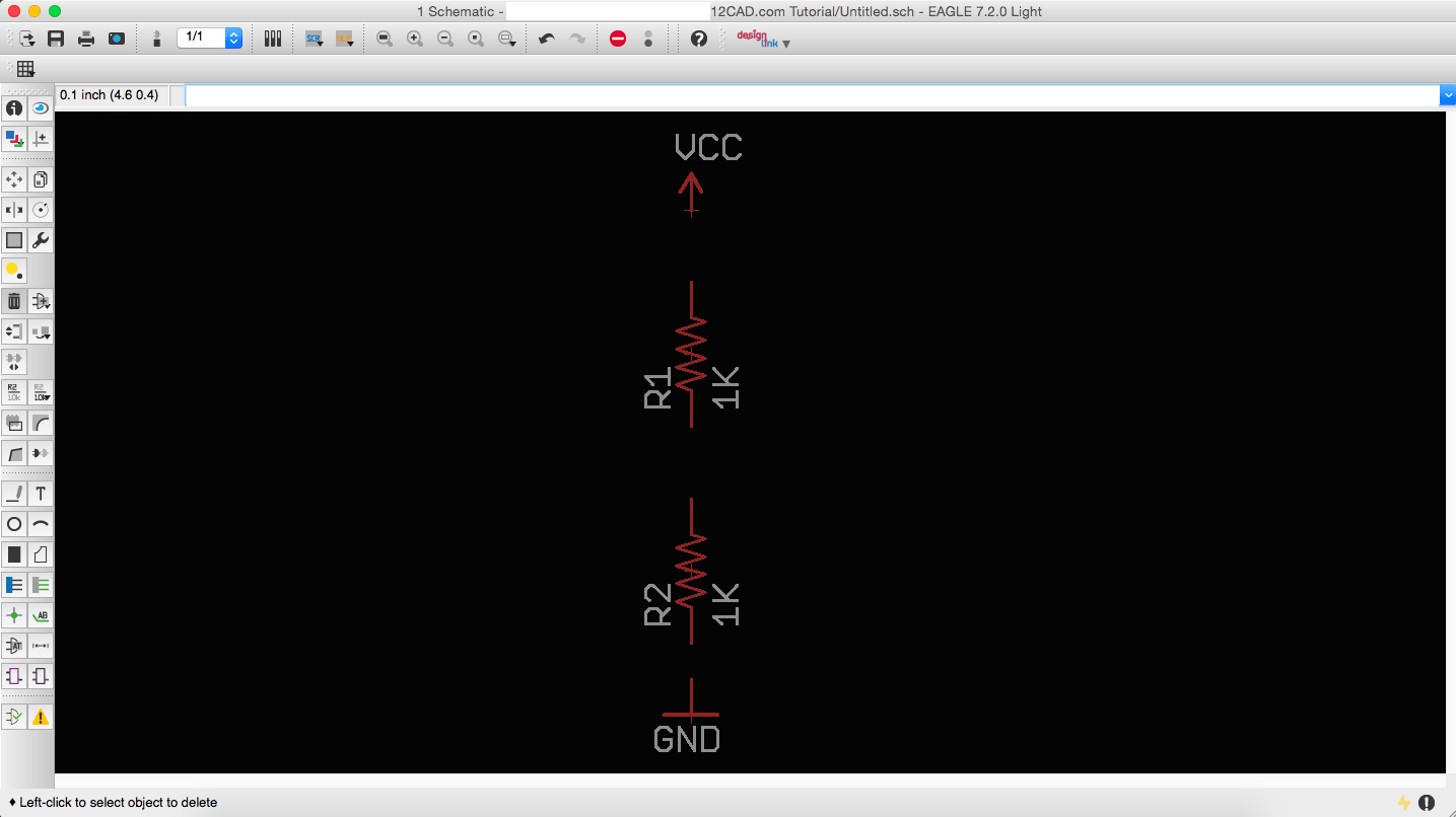
After finding the parts, the schematic window should look similar to Figure 2 below. I added the parts and rearranged them by moving and rotating them. Now, we can start adding the electrical connections (nets).
How to draw an Electrical Connection (Net)
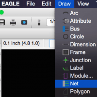
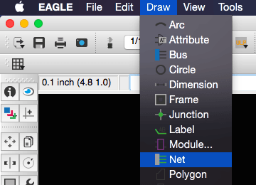
If you were able to replicate Figure 2 successfully, you can now start adding nets to the schematic. The add an electrical connection option is located in the left toolbar or the Draw menu. See Figure 3 and Figure 4 below for the locations.

To create an electrical connection, follow these steps:
- Click on the ‘add a net‘ option (Figure 3 or Figure 4)
- Click on the end of a part, e.g. one end of a resistor
- Green line will appear where you clicked. Now, click on another part’s end to make a connection
- Repeat steps 1 to 3 for all potential connections
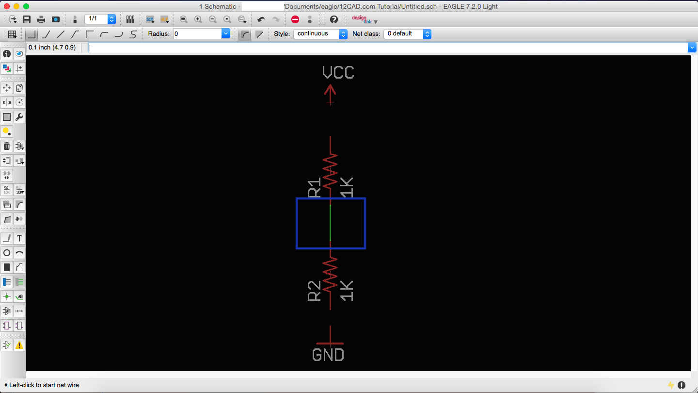
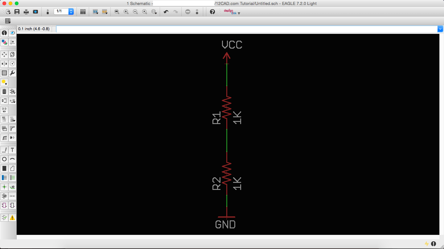
An example of connecting the two resistors is shown below in Figure 5.
All the parts should be connected together in series. If you think of this in terms of electricity flow, if you miss one of the connections, you will have no flow. The final outcome should look similar to Figure 6 below.
How to add a Net Junction
If you refer to Figure 1 of the voltage divider, you will see that Vout is branching out between the two resistors. The point in between the two resistors will most likely connect to other parts of your circuit. Therefore, we need to add a junction which a net can connect to.
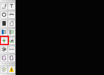
The junction option is located in the left toolbar and also in the Draw menu. Below is Figure 7 showing the location of the junction in the toolbar.
To add a junction, follow these steps:
- Click on the junction option (Figure 7)
- Find the location where you want to add the junction and click.
- A green junction circle will appear
- Click on the add a net connection option (Figure 3 and Figure 4)
- Click on the prior create junction and an electrical connection will appear. Drag the wire and click at your desired location on the schematic.
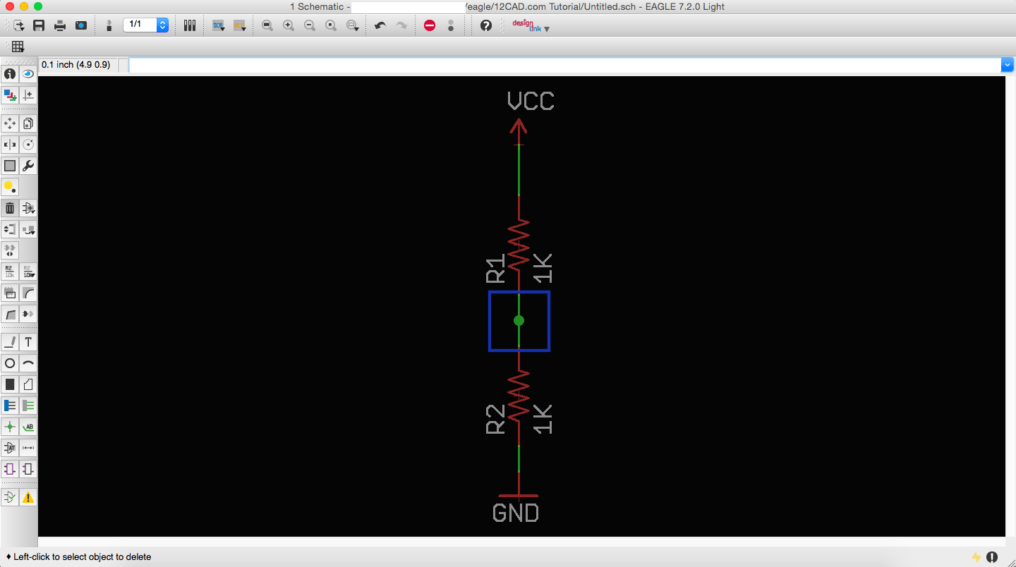
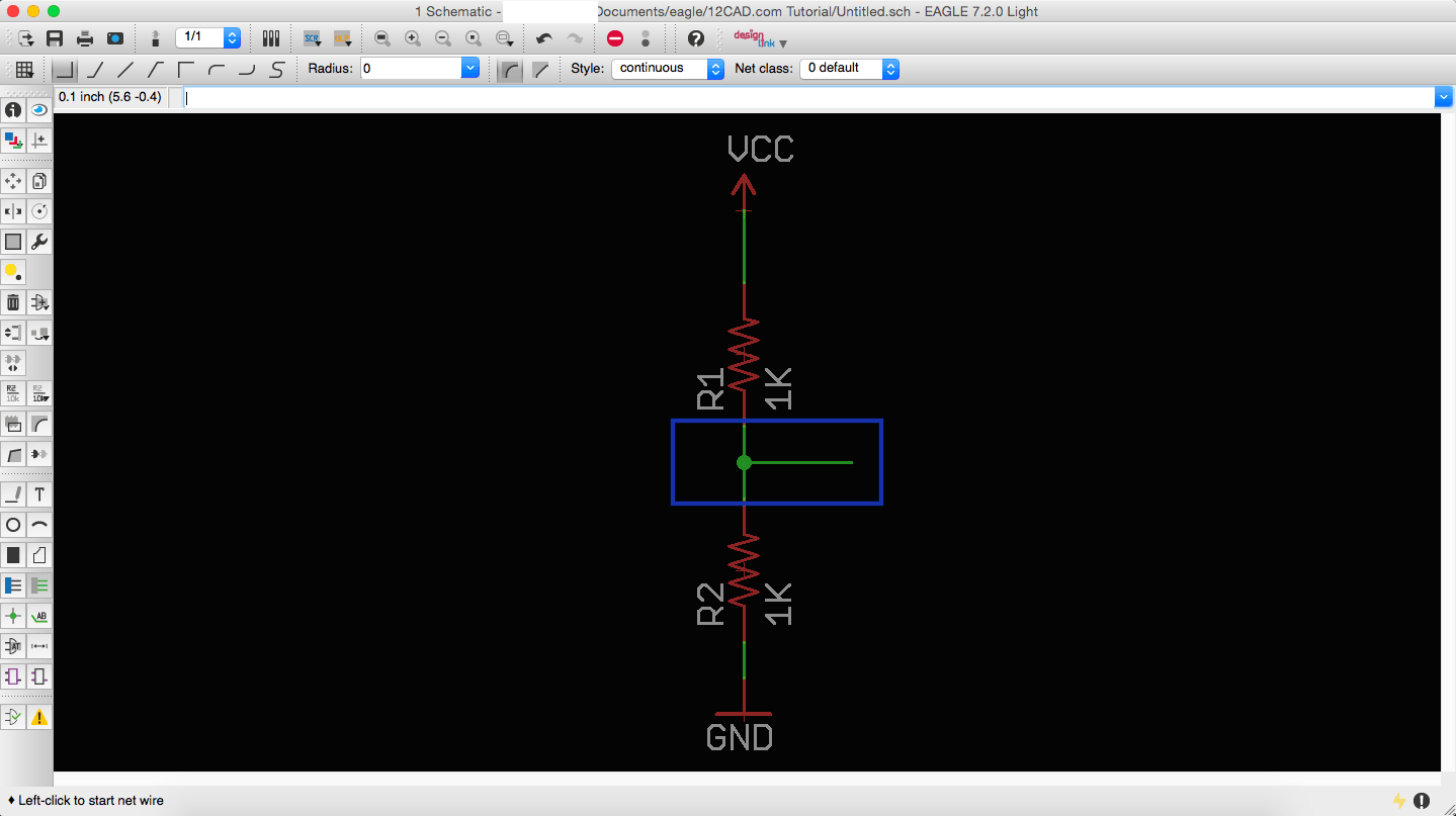
Steps 1 to 3 are shown in Figure 8 below. Steps 4 and 5 are shown in Figure 9 below.
You have successfully creating a voltage divider in this Eagle schematic tutorial.
Video tutorial of Adding an Electrical Connection
In this video, I explain the step-by-step procedure outlined in this tutorial. I also go into more depth on how to label the Vout node. Check it out.
http://youtu.be/fXJ78nna0es
Final Thoughts
Electrical net connections are one of the most important aspects of designing a PCB in Eagle. Without them, the PCB would be unaware of the flow of electricity. In this tutorial, I discussed how to add electrical connections to an Eagle schematic using the voltage divider as an example. In addition, I also covered how to create junctions.
Did you have any difficulties with this tutorial? Please share your thoughts and/or difficulties by leaving a comment below.

