This is the first tutorial in the complete PCB design tutorial set. I will cover three basic aspects of Eagle PCB. They include creating a project, adding a library, and lastly, creating a schematic. After following these steps, you will know how to start off a new project and at the same time, understand the software’s options. A step-by-step procedure is discussed below and a video tutorial is also provided at the end of this tutorial.
Before we begin, make sure to download the software. If you need help with installation, please browse the Eagle website for instructions. Next, determine a location where you would like to save your PCB files. Make sure this location is accessible.
What will you learn?
The topics covered in this tutorial are listed below and if desired, you can skip to specific topic by clicking on it. In general, I will teach you how to setup Eagle efficiently for any project.
[toc]
Creating a New Project in Eagle PCB
I am using a Macbook Pro laptop, however, the same menus exist for Windows 7/8 operating systems. To create a project, follow these steps:
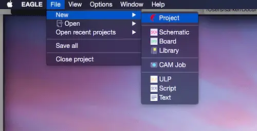
- Click on File -> New -> Project
- A dialog box will open. Find the location to save the project.
- Name the project and click ‘Save’.
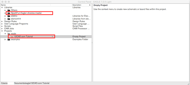
I named my project ‘12CAD.com Tutorial‘. You can name the project however you would like. If these steps are successful, you should see the project in the Eagle Control Panel under Project option. The next image (Figure 2) shows this clearly.
In the below image (Figure 2), the control panel is shown. This includes a list of all of your projects and component libraries. The other options are not relevant at this moment. By expanding the Projects, you can see the 12CAD.com Tutorial. If you can see your project name here, then you have completed the first step!
How to Add Libraries to Eagle PCB
A PCB requires the use of components. Components are resistors, capacitors, integrated circuits (ICs), and much more. In general, components are the core elements to creating a PCB. I will use the Sparkfun Eagle Library, which I highly recommend. They have an excellent selection of elements which you can buy from their website and use to create your PCB.
- Download the library, or any other library that is similar
- Open your Eagle PCB folder.
- If Apple Mac, this will be in the Applications folder.
- If Windows, this will be in the Program Files folder
- Open the directory lbr. Here you will see default libraries included with the software
- Add the Sparkfun Library folder into the lbr folder
- Restart the Eagle software
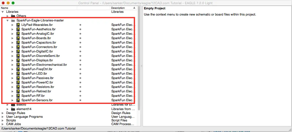
- If successful, Sparkfun Eagle Libraries options should appear under Libraries (see Figure 2 and Figure 3)
The different components available in the library can be seen in Figure 3. Your library should look similar. If it does, you have successfully added a library to Eagle. Good job!
How to Create a New Schematic in PCB Design Software
The last step in this setup tutorial is creating a new schematic. The schematic is the most important aspect of the PCB, which allows you to make a layout of your circuit. It dictates which components will be in your circuit and how they are connected. Each project, in this case, 12CAD.com Tutorial must have a schematic attached to it. To do so, follow these steps:
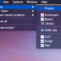
- Click on File -> New -> Schematic (Figure 4)
- A new window should appear. This is the schematic window (Figure 5).
- Make sure to save (File -> Save As) after the schematic window appears
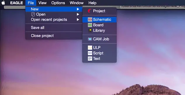
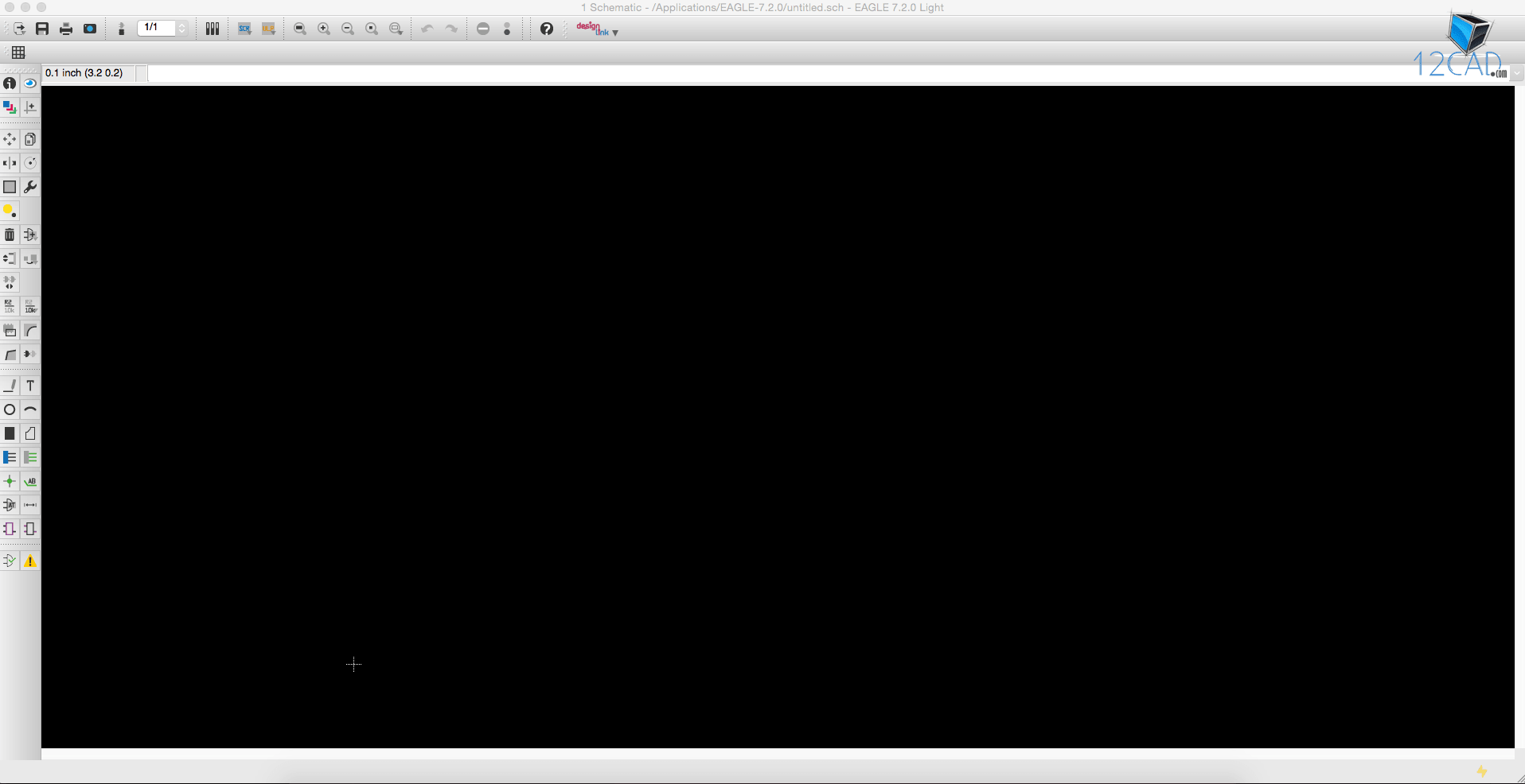
Figure 5 above shows the schematic window. I will discuss the important options and menus in this window in a later tutorial. If you are able to view the schematic, you have successfully finished the first tutorial. I encourage you to watch the video below. It will give you a more in-depth explanation and guide you through the process.
Video Tutorial: Create Project, Add Libraries, and Create Schematic in Eagle PCB
For a detailed tutorial on these aspects, you can view the video below.
Did you have any difficulties with this tutorial? Please share your thoughts and/or difficulties by leaving a comment below.


Comments
One response to “Creating Projects, Library, and Schematics – PCB Tutorial”
[…] be explained in detail in this tutorial. You can check out the previous tutorials to understand how to create a schematic and also the explanation of menus and toolbars in the […]