If you’re into 3D printing, you need STL files to print with. And if you’ve developed your own designs, then converting DWG to STL format is your next step. You might want 3D printed parts for the following or other reasons:
- Visualize design concepts
- Create product mockups, architectural models, and terrain models
- Test form, fit, and function
- Identify design problems
- Create masters for vacuum forming applications
- Create Marketing tools
 For many software packages, built-in solutions exist and for AutoCAD a simple command can set you on your way. Read on for the different ways in which you can convert DWG to STL format.
Command Line
Using the command line interface, you can create STL files from your DWG AutoCAD designs. The “STLOUT” command asks you to select the 3D element(s) and saves an STL file of the design. File name will be originalfilename.stl.
Menu Bar
Using the menu bar, navigate to “Output” and then from the “Send” option to the “Export” option. Within the Export option, either the drop down context menu will have an “Export to STL” option. Or you will be able to select STL from the dropdown selection box on the next dialogue box for saving the file. Enter the name of the file as you want it to be saved, (default will be originalfilename.stl). In some versions, or because of exporting plug-ins, the format selection option may not have “STL” and instead may read “Sterolitheography File”.
Bonus Pointers for Converting DWG to STL
Autodesk Inventor
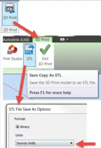
From within inventor, the “Save Copy As” option will allow you to save the file as an STL. Within the options, select “High” for quality/rendering and hit “Save”.
Converting DWG to VRML
CADSTudio has come out with its proprietary solution for creating Virtual Reality Markup Language (VRML) files and allows AutoCAD users to add the solution to their environments. With just a few selections for output, a VRML of your selected models will save in the projects home directory. The name of the solution is VRMLOut.
Conclusion
Converting DWG to STL format requires a significant amount of manipulation and processing, hence for the process to complete, the 3D solid data is converted in to a faceted mesh constituting of polygons that are optimized for printing hardware. For achieving greater detail the “FACETRES” system variable can be changed to increase or decrease the number of faces when generating the STL file.


