CATIA (Computer Aided Three-dimensional Interactive Application) is one amongst CAD software that was initially developed to help design aviation systems. It is today one of the leading CAD software in aviation and automobile industry.
Here is a very basic “Demo” about Basic commands in CATIA. In this post we will discuss exclusively commands related to Part Design workbench.
When it is required to make a simple solid component, we usually go to Part Design workbench. Important commands in this workbench include PAD, POCKET, SHAFT, GROOVE, RIB and SLOT.
All these commands come under a toolbar, named Sketch-Based Features. That means, we are required to have a Sketch to make use of a particular command. Let’s see how each of these command are used.
PAD command
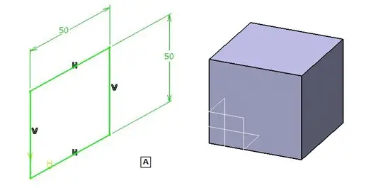
In most CAD software, the equivalent of this is called EXTRUDE, but in CATIA we call it PAD. PAD command adds material in the third direction, a direction other than the sketch. The cube below was made using the PAD command.
POCKET command
In CATIA,The POCKET command is somehow the opposite of PAD command. It simply helps remove geometry belonging to an already create part.
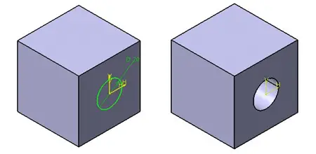
On the figure below the POCKET command is helping us to create the cylindrical hole in the middle of the cube.
SHAFT command
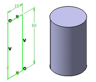
Similar to REVOLVE command in other CAD software, the SHAFT command is mostly used to make shaft like parts. It requires an axis, around which the sketch will be revolved.
GROOVE command
As said earlier, there is another command in CATIA to subtract geometry from shaft like components, called GROOVE. This command allows you to remove material by revolving a sketch.
RIB command
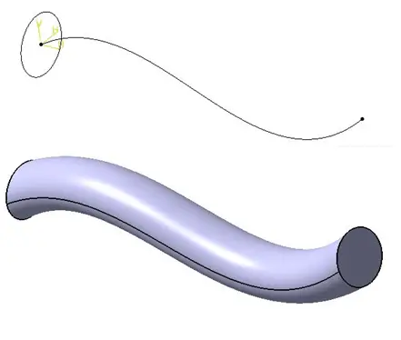
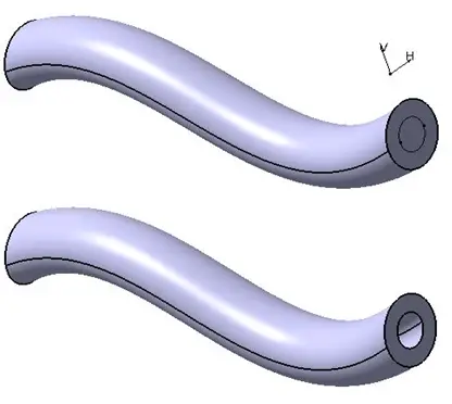
The command which is usually known as SWEEP is called RIB in CATIA. It adds material along a guide curve (which can be a straight line, arc or may be a spline). RID is used to make components like springs, pipes etc.
SLOT command
Slot removes the material along a guide curve. Here is an example of slot.
While using SLOT, I have used the same guide curve that was used for RIB. This ensures that the cross section will be uniform throughout.
Note: In Part Design workbench, when you click on Sketch ![]() , the workbench will change to Sketcher. To return from Sketcher to Part Design, you have to exit workbench using
, the workbench will change to Sketcher. To return from Sketcher to Part Design, you have to exit workbench using ![]() option.
option.
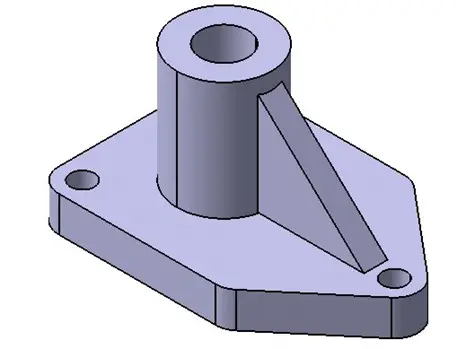
Now that you have learned basic but important commands from Part Design workbench. Try creating an object using these technique.



Comments
2 responses to “Basic commands in CATIA”
haw can i make thread in using catia
catia uses company tell me please