Whether you are specifying dimensions for a large machined component, trying to develop assembly instructions for an assembly with many components, or need to provide non-standard views to fully define a feature, SolidWorks has the 2D drawing tools you need to produce clean, properly defined drawings.
In this tutorial, we will look at how to implement three useful types drawing views in SolidWorks to accurately portray features and dimensions for components.
We’ll review Detail Views, Section Views, and Broken Views, which are the most used views of all possible views in SolidWorks. As an example, we’ll use a two-piece plastic container and lid assembly, held together with four screws. Let’s take a look.
Detail Views
Detail Views come in handy very often. It’s often the case that drawings with many dimensions or annotation become overcrowded, and you may find that it is difficult to see where dimension lines point on a small feature among a forest of other lines and arrows on a drawing.
This can occur when you are limited by page size – for example, if your customer or company requires you to place drawings for larger components on an A-Size drawing template for filing purposes, or you have a large part with one or more relatively small features.
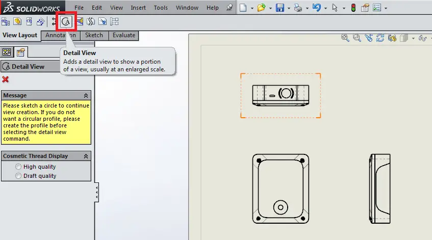
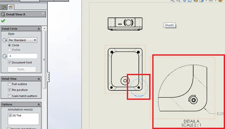
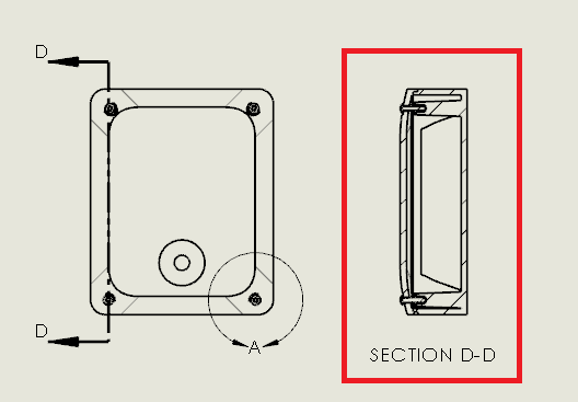
With a standard view already placed on the drawing, select Detail View, located in the View Layout tab of your drawing. Selecting the button will allow you to sketch a circle around an area of interest.
Notice that you can place the detail view anywhere on your drawing. You can even edit the Style in the View Properties manager, to specify how the detail view circle is displayed, the name of the view, and even the scaling.
Section Views
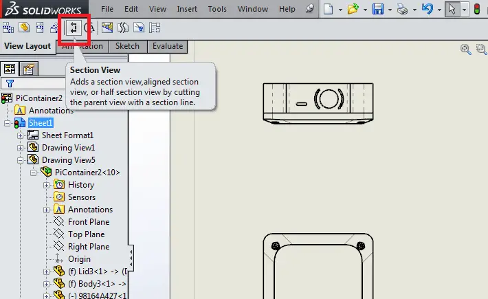
Section Views are versatile view types in which an existing view is intersected by a Section Line, thereby providing a view of the cut section. This is useful when it is necessary to “cut a part” to dimension or portray it through material which would otherwise obscure the view.
Note that depending on your version of SolidWorks, this and other types of Views may look slightly different when implementing, but all should function very much in the same manner.
When creating the section view, move the cursor to the relevant location on the part or assembly, click, and then place the resulting view on the drawing.
Note that you can also combine multiple types of view – for example, you are able to create a detail view on section view, which can be very useful!
Broken Views
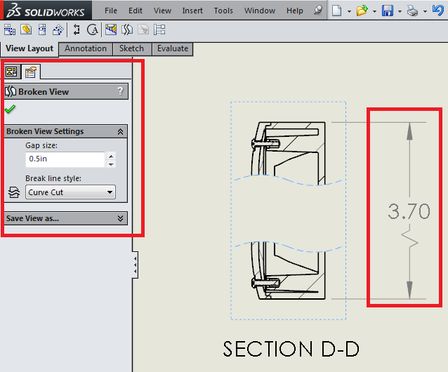
Broken Views are most useful for parts which are too long in one direction to fit on a drawing, or which have no relevant dimensioned features between linear sections of parts.
This might be used for extruded parts, for example, where the overall length of the part is needed, but would not otherwise fit on your drawing.
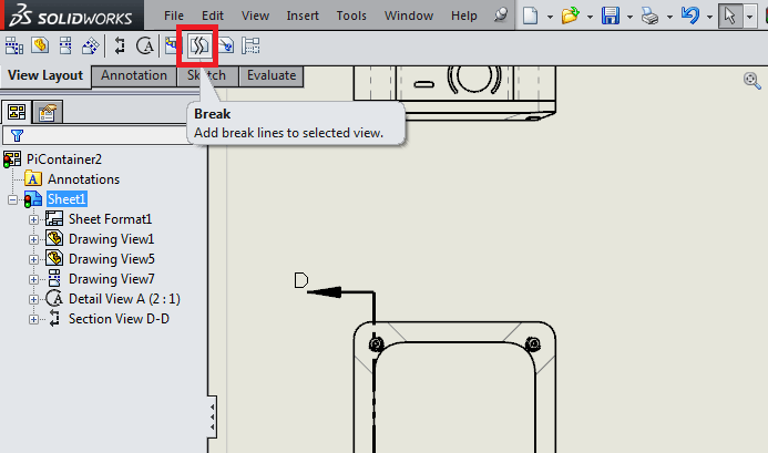
Select Broken View in the View Layout tab.
Select the view you would like to break. Then, choose whether or not your break is horizontal or vertical, and click in two locations on your chosen view to break the part. Adjust the lines by clicking and dragging them until you’re satisfied with the broken view.
Note that you can change the type of line used to break the part to suit your desired convention. Also note that any dimension spanning the break will be displayed with a jog for indication.
That’s all for this tutorial. The next time you need to specify a special view on a drawing, keep these tools in mind. Check out other tutorials about SolidWorks to apply such drawing views to actual designs, i.e. try this cosmetic threads tutorial. Good luck!

