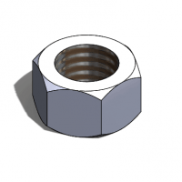
In this tutorial, we’re going to take a look at creating a basic piece of hardware in Solidworks – the hex nut. This simple piece of hardware can be extremely useful when modeling assemblies which are bolted together.
As you’ll see, creating an accurate model for a hex nut is not very difficult. Let’s take a look!
How to Create a Nut
- First, create a new part.
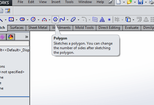
- Now, create a Polygon sketch on the Top Plane.
Notice that by default, SolidWorks will create a hexagon. This will be perfect for creating the hex nut.

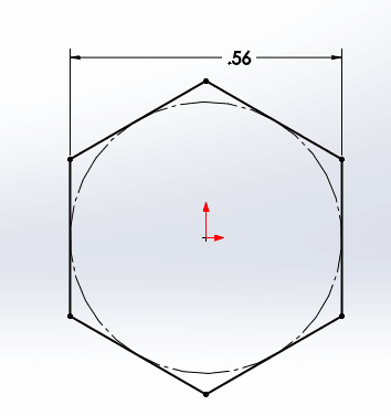
- Dimension the width of the polygon. In this case, we’ll be using standard dimensions for a 3/8” nut, for which the width is approximately 9/16.”
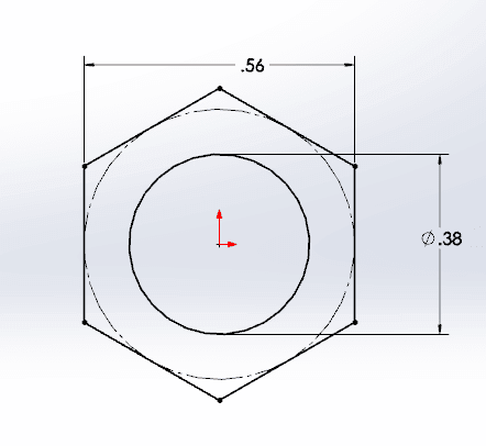
- Now, add a 3/8” circle to the center of the hexagon. This completes the basic shape for the hex nut.
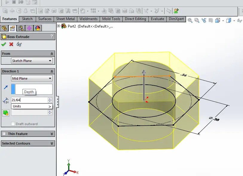
- As you might expect, we’ll now use the Extrude Boss / Base feature to extrude the profile of the nut. Use 21/64” for the depth.
- Select Mid Plane from the dropdown menu under Direction 1. This will change the Extrude feature such that its depth is split down the middle of the Top Plane.
- Select OK.
- Select the top face of the hex nut.
- Sketch a circle on this face, using the origin as a center point.
- Select the circle, and an edge of the hexagon extrude, and select the Tangent relation between the two.
This will create a circle that is tangent to the outside edges of the hex nut. We’ll use this to create the rounded detail along these edges.
- Select Extrude Cut.
- Select the “Flip side to cut” option
- Select the Draft button, just below the “Flip side to cut” text, and input 45 degrees into the field.
- Select OK.
Mirror the Nut
Now, we’ll mirror this feature to the other side of the part. This will be easy, since the Top Plane runs through the center of the part. This is the primary reason for the Mid Plane option when extruding the overall shape of the hex nut.
- Select Mirror
- Select the Top Plane as the Mirror Face / Plane
- Select the Cut Extrude feature created in the previous feature step as the “Feature to Mirror”
- Select OK.
Simulate Threads
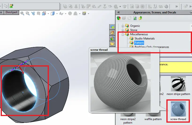
Now, we’ll add a visual texture to simulate threads on the inside of the nut. Note that you can model true threads into the part using the Helix and Swept Cut features. However, for most purposes, this is an unnecessary step that adds to the file size and complexity of the part. In most cases, it is sufficient to simply represent the feature using a texture.
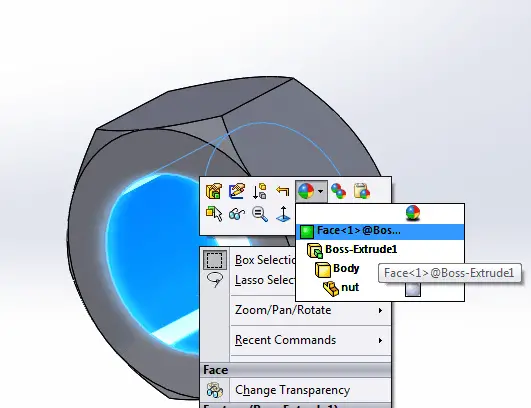
- Select the inside face of the hole in the nut.
- Right click, and select the Appearances drop down menu.
- Select the top option, specifying that you are editing the appearance of this Face.
- On the right side of the screen, navigate through the folder tree to the Miscellaneous > Pattern > screw thread
- On the left side of the screen, select the Advanced
- Select the Mapping
- Scroll down to the Size / Orientation section, and input 2.0in into the height or width field.
By default, “Fixed aspect ratio” is selected, causing the height and width to move proportionately with each other as one or the other is modified.
Final Thoughts
That’s it! Congratulations, you’ve created a simple but effective 3/8” hex nut for use in your assemblies. Making a nut is a very important skill to have in SolidWorks. Be sure to check out the other great tutorials for SolidWorks as well.