
Welcome to Day #18.
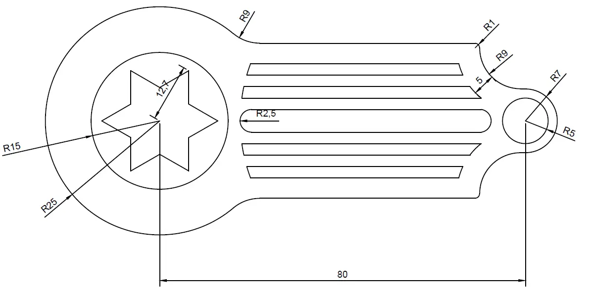
Today’s AutoCAD exercise consists of the following. We have this simple figure to replicate given all dimensions.

Complementary information
Today’s exercise have been conceived with the aim to have you use all what you have learned so far. But we will have to draw our first polygon today.
The 6 point start in the design is easily replicated using a polygon with 6 sides. You might want to check how to draw a 5 point start in AutoCAD to apprehend how you can go about this.
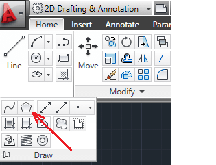
The POLYGON command
Notice that the star is Circumscribed about the circle of R12.7 in our exercise.
There is actually two ways to draw a polygon in AutoCAD: Inscribed in circle/Circumscribed about circle. And the information you need to provide will be, the center and the radius of the circumscribed circle or inscribed circle. Play around with both possibilities and notice the difference.
You are free to use whatever technique you master best to have this exercise done, but I will suggest you explore and trying different things for experiment sake.
Feel free to drop a comment if you don’t understand something in today’s exercise. Like this if it helped you, and see you on the next 2D AutoCAD exercise.

[ws_table id=”3″]
Comments
15 responses to “20 Days of 2D AutoCAD exercises #18”
I think you have a measurement wrong.
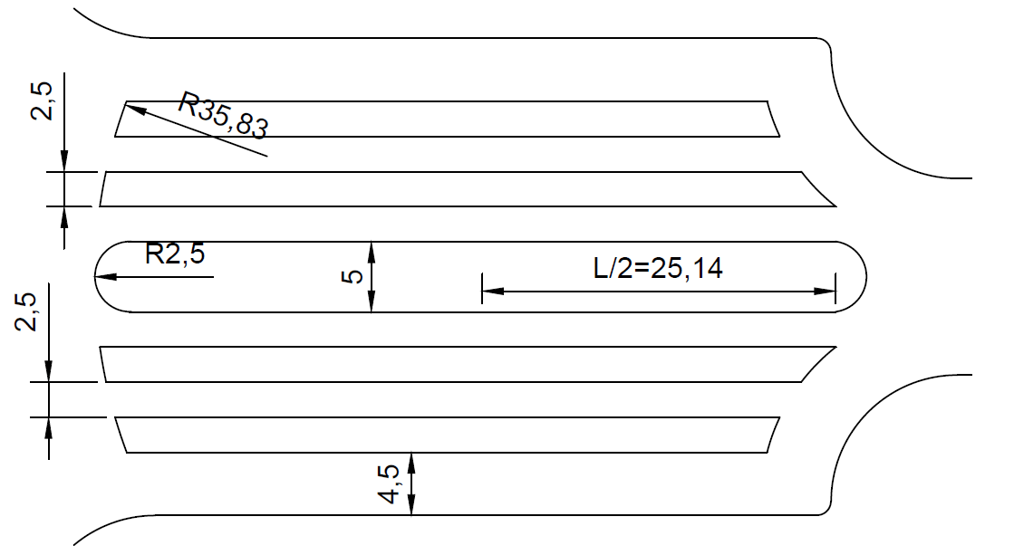
The horizontal lines are spaced 2.5 and 4.5.
All of those added together equal 34 or 17×2.
The 2 radius’s, 9 and 7 equal 16.
I think that 9 radius should be 10.
Is that correct or am i missing something?
You surely are making a mistake. The horizontal lines are spaced by 4.5 for the ones at the sides (up and down), and 2.5 for ones in between
I think theres something wrong here but finally I figured it out with my own.
thanks
Nice!
How do you know the lengths and starting positions of all the 5 shapes between the star and the circle at he other side of the drawing. I can’t get my head round it!!
check the post https://www.computeraideddesignguide.com/draw-a-5-point-star-in-autocad/
Is there something what I´m too blind to see? I can´t draw it, it seems like there is one measurment missing. It´s not the start what I have problems with but the right side of this drawing. Where are the centers for the circles that I have to draw?
Can somebody please be so kind to explain this drawing to me?
I am not sure if I did this correctly but here is what I did.
First, the polygon is inscribed, not circumscribed.
For the circle with radius 35.83, I knew the center would be on the axis of symmetry. We know the distance is 80 between the two circles on the ends. So I did 80 – 9.5 – 2(25.14) – 2.5 + 35.83 to find the x-coordinate of its center, 53.55 The circle with R15 I centered at the origin, so this circle has a center of (53.55 , 0).
For the straight lines, I used the Quadrant on the R9 circles on the right, and extended the line from there until it intersected the R25 circle on the left.
For the right side of the horizontal bars though, I think I am absolutely wrong. I used an offset of 5 on the R9 circles, however they look off to me based on the original. I assumed the centers of the circles on the right are vertically aligned, but I think I was wrong to make that assumption.
Any insight is welcome 🙂
Hi Mira, I think we can give up on this drawing because there is some essential data missing so I strongly assume that the author forgot to provide us with some measures. The results of the data above will never get you to the same picture so don´t waste your time with this drawing cause it will be negative training.
Hello. I actually figured it out. My assumption about the centers being vertically aligned was correct. The top and bottom straight lines are 1 unit displaced from the R9 circle’s center, however. That could be inferred from the original measurements Antone gave because the total distance between the horizontal lines can be calculated to be 34 = 2(4.5) + 8(2.5). I originally assumed the top and bottom lines were horizontally aligned with the R9 circles’ centers, but that gives a total distance of 32.
Where do you get the numbers to get the origin of the radius 35.83 circle?
I think I nailed this drawing, even though I feel like some measure there might be missing, I was able to assume where to place the R35,83 circle. Thing is, I started by making the R9 Circles that are vertically alligned with the R5 and R7 circles, all you have to do is make a line that measures 9 and starts vertically alligned with the R7 circle center from the border outwards. repeat or mirror for the other circle; Then I made a line from the borders of the R7 to R15 Circles. That line should measure 60. Then, just make a line from the center of the previous line to the left that measures the 25,14. You can delete the 60 line. Create the R2,5 circle at the edge of the 25,14 line and then you can create a circle with R35,83, It doesn’t matter where ’cause then you just have to use Move, and relocate it so that it’s tangent to the R2,5 circle, whereas the center must be horizontally alligned with the R25, R15, R7, R5 and R2,5 circles. then you just have to repeat the 25,14 line to the right and make the other R2,5 circle. I think you can figure out out to make the other lines. I hope I was helpfull, sorry if I am confusing, english isn’t my mother language but I am happy to provide with help and prt scs if need be ^^
Do you use the metric system on the tutorials or inches?.
I can’t find any reference to what system you use and I would like to use the same as you.
Thanks.